Project Introduction
"Water pump" is a machine that transports liquid or pressurizes liquid. It can be seen everywhere in our lives. It is mainly used for urban water supply, sewage system, agricultural water conservancy system, power station system, chemical system, etc. At present, most water pump management is operated by manual patrol, which is time-consuming and cannot be in place in time. Once a failure occurs, the problem cannot be eliminated in the first time and the normal water supply cannot be quickly restored.
With the development of the IoT industry, pump control is no longer limited to manual duty. Remote water pump control uses sensors to detect the real-time water level to control the start or stop of the water pump. If the master-slave system fails to detect each other's heartbeat signal during operation, the currently executed start command will be stopped and an alarm will be issued. The V-BOX device performs data transmission through the 4G network to achieve real-time feedback of alarm information.

Process Requirements
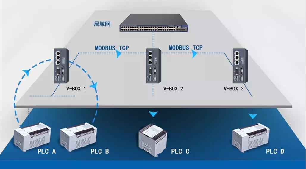
Two sets of control systems, each of which is 1 master and 4 slaves, collect the liquid level of the pool centrally, and remotely control the start and stop of the pumps of each slave station to achieve centralized control management. Although the process is simple, a variety of external factors need to be considered. When writing a program, a variety of possible situations need to be considered, and an early warning prompt is provided on the interface. such as:
●If there is a problem with the liquid level at the centralized end, it is necessary to judge whether the sensor is disconnected.
●If the device data is interrupted, it is necessary to judge whether the V-BOX on the centralized end is offline or the PLC stops running.
●If the device data cannot be updated, it is necessary to judge whether the V-BOX on the control end is offline or the PLC stops running.
Case Analysis
In general, the solution is to exchange data between 4 PLCs through V-BOX. The centralized control end selects the more powerful Smart V-BOX S-4G, the control end selects the cost-effective E-4G, and the control system PLC selects LX3V- 0806MR-A, select LX3V-2ADI-BD for analog data acquisition, select PI3102i for HMI of control interface.
Program Introduction
1. First, you need to plan the data parameters that the system needs to interact.
2. Address correspondence: data is mapped in double word shaping. For example, in the control address given by the host to the slave, the low byte has heartbeat data and real-time data; the high byte has control words, including start, stop and fault reset. The address mapping function of V-BOX is to write the constantly changing data in real time and effectively, and can obtain bidirectional real-time data read and write operations to ensure the success of the mapping.

3. The program segment of the host PLC: If the host PLC fails to receive the heartbeat change from the slave PLC for a certain period of time, it will output an alarm.
4. The program segment of the slave PLC: The slave PLC fails to receive the heartbeat change of the master PLC for a period of time, and the slave PLC stops the equipment.
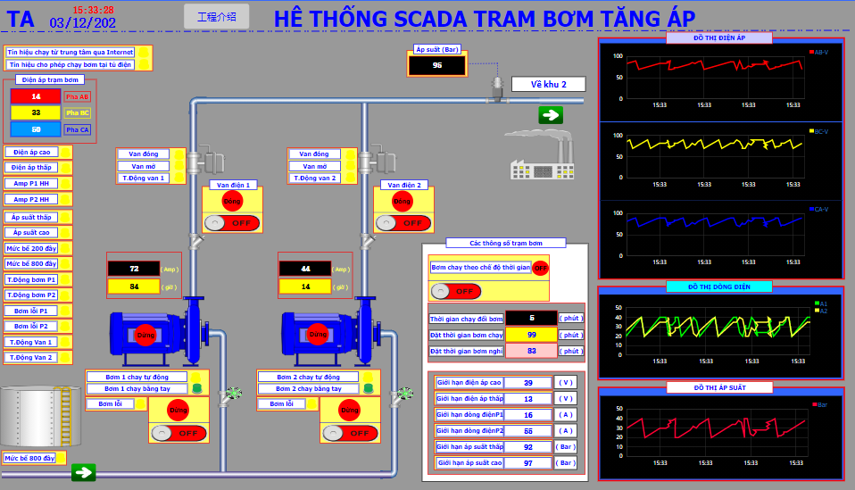
HMI Screen