Brief Introduction
The
automatic sticking machine cuts and glues the plywood to a certain depth through
a preset tool, and then conforms to the wooden strip sent by the servo, in last
to form a woodworking product.
Process Requirement
Based on the control
of the strip device technology, six new stepper motor controls are added to
achieve the tool distance setting function, which can be quickly move to a
preset distance to achieve precise control.
Solution Analysis
The
control system adopts the HMI LEVI2070D, and the PLC LX3V-1616MR2H and two
LX3V-4PG expansion modules.
Reasons for selection: Woodworking machinery
mostly uses relay type PLC as the main control, and directly controls
peripherals such as solenoid valves or inverters. At the same time, the customer
requires compatibility with the previous control scheme, and the tool can be
changed to mechanical manual tool setting.
Therefore, in the selection, the number of
relay points of LX3V-1616MR2H meets the requirements. In the aspect of 6 tool
control, the LX3V-4PG expansion module can be used uniformly to meet the
requirements. Based on the above factors, the selection configuration was
carried out.
Main control principle: The original servo control still uses
the output point on the PLC for control. The original program does not change.
The new program only increases the control of the LX3V-4PG to 6 stepping
motors.
To realize the fixed-length operation control of the stepping motor
in the program, it is necessary to have all functions such as finding the
origin, manually jogging, manual shifting, and automatic running. Provide
debuggers with as many modes of operation as possible to achieve the best
debugging results and user experience.
Program Brief
Introduction
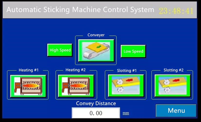
HMI program
Main Page

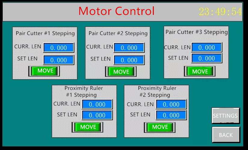
Motor Setting Page

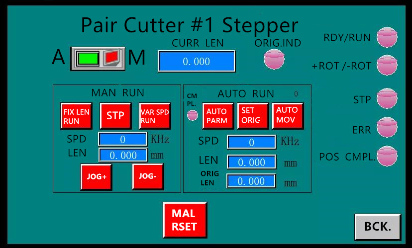
Detailed Debugging Screen of One of the
Stepper Motors

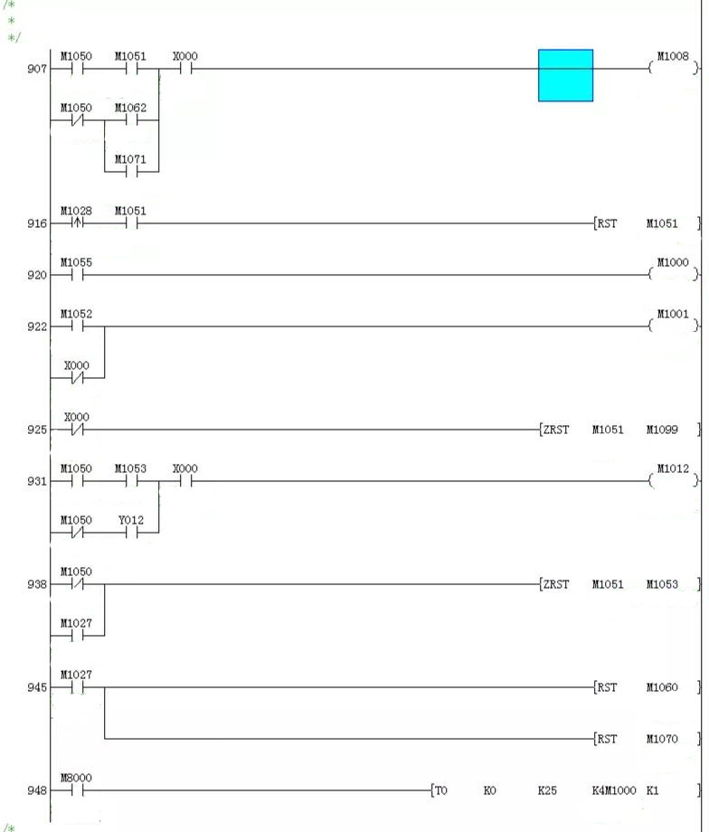
PLC Program
LX3V-4PG Manuel Setting


Project Summary
During the
debugging, there was a problem that the positioning of the stepping motor was
inaccurate. After many tests, the solution was found. That is, it is necessary
to connect a 2K resistor in series between the pulse and direction of the
stepping motor. This has something to do with the brand of the driver of
different stepping motors. It is recommended that the customer do the serial
processing regardless of the brand to ensure the accurate operation of the
equipment.
This debugging summarizes the following
points:
1.Select the plan according to the needs, not only considering the
cost, but also the compatibility of the general program.
2.For the LX3V-4PG
expansion module, it is necessary to pre-plan the address. The control
requirements of the six stepper motors are the same, but the addresses are
different. If you can pre-plan the addresses nicely, you can get twice the
result with half the effort.
3.For problems that arise during debugging, be
sure to check them from start to end, eliminate the factors of the problems one
by one, and finally fix the problems.